Creating a Project in PyAMS
A project in PyAMS is a schematic of an electronic circuit together with its models and the analysis settings required to simulate it.
Steps to Create a New Project
Open PyAMS and choose .
Save the file into your Folder Workspace/ where all project files will be stored (see
fig_new_project).
From the menu, select the Project file type (see
fig_type_project).
A models folder is created automatically inside
Workspace/modelsonce you set the file type to Project.You can modify or add new models and symbols using the Symbol Editor.
Returning to PyAMS, open your file project in Workspace/. You will find your models available in the Library Browser under Project [models].
From the Library Browser, drag and drop models onto the schematic (see
fig_place_models).
Use the Wire/Net tool to connect component pins.
Add Sources, Ground, and Probes as required for measurements.
Insert a PyCode block to enable simulation by analysis with Python.
In the PyCode dialog: - The first page shows the generated circuit code (read-only). - The second page allows you to extend the analysis using Python,
pyams-lib, and any user-installed packages (seefig_pycode_dialog).
Open Analysis Settings and choose the required analysis types: DC, AC, Transient, etc. (see
fig_analysis_setup).Define start/stop values, steps, initial conditions, and output variables.
Click Run to execute the configured analyses (see
fig_run_sim).If a PyCode block is present, it will also execute any custom computations.
Figures
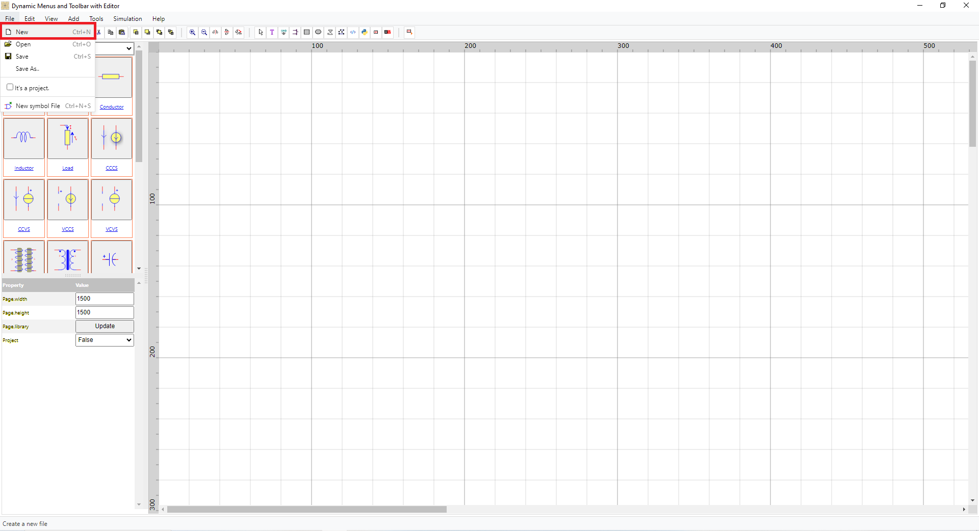
Figure 1 – Creating a new project in PyAMS.
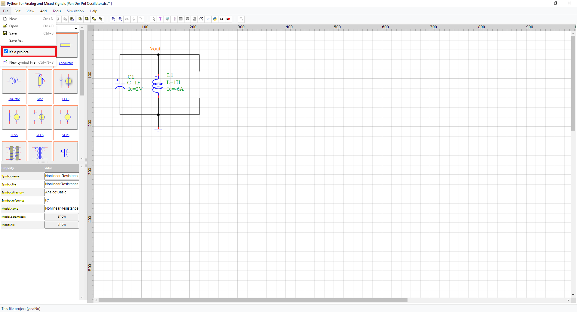
Figure 2 – Converting a file to a PyAMS project.
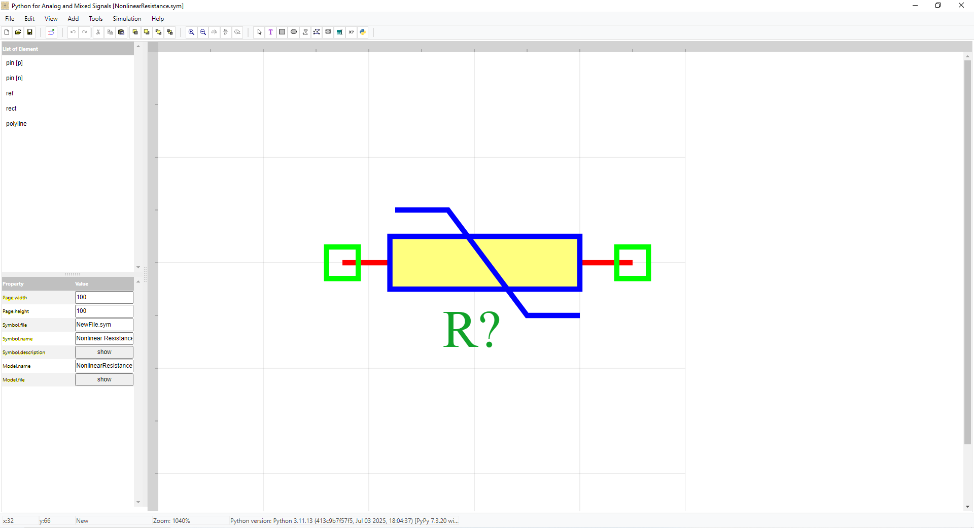
Figure 3 – creat symbol.
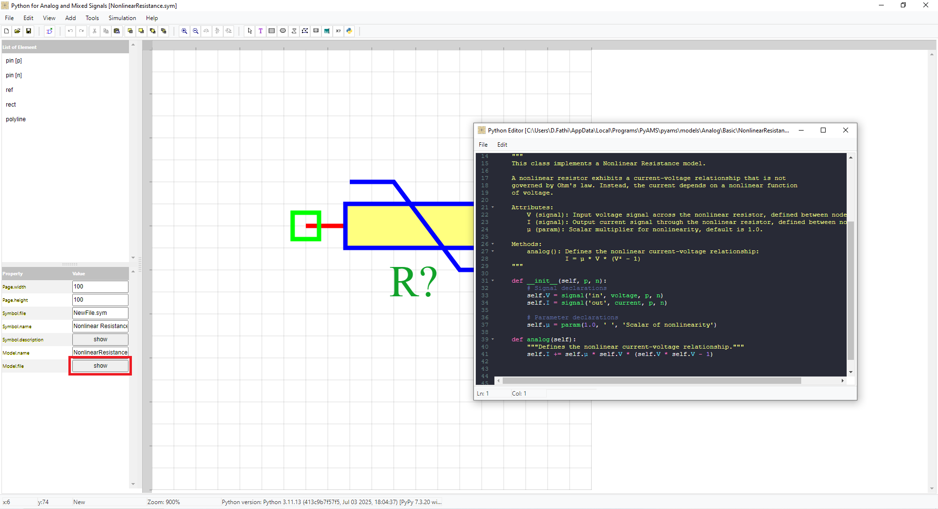
Figure 4 – creat model.
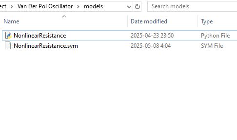
Figure 5 – the models saved in Workspace/models.
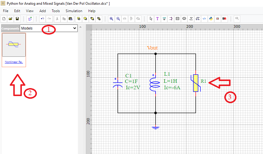
Figure 6 – Placing models from the library into the schematic.
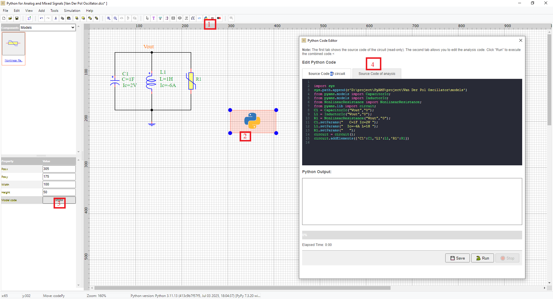
Figure 7 – PyCode dialog: read-only circuit code (page 1) and Python analysis (page 2).
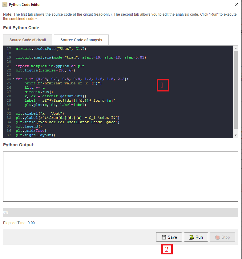
Figure 8 – Configuring DC/AC/Transient analyses.
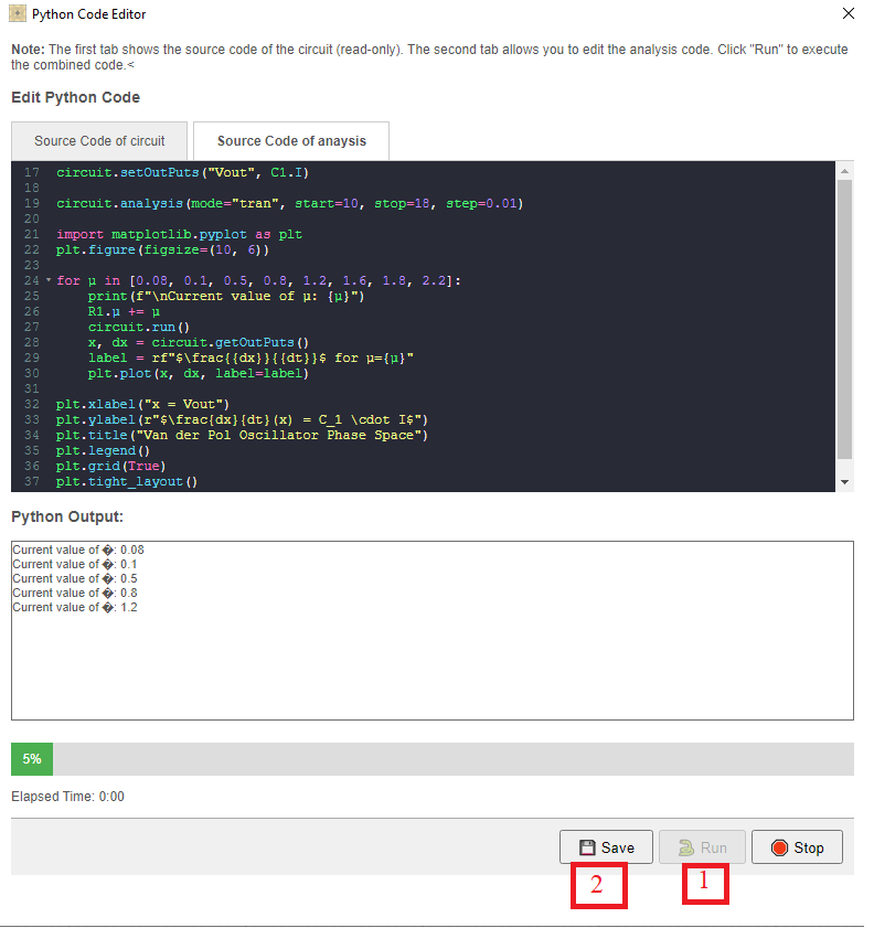
Figure 9 – Running the simulation.
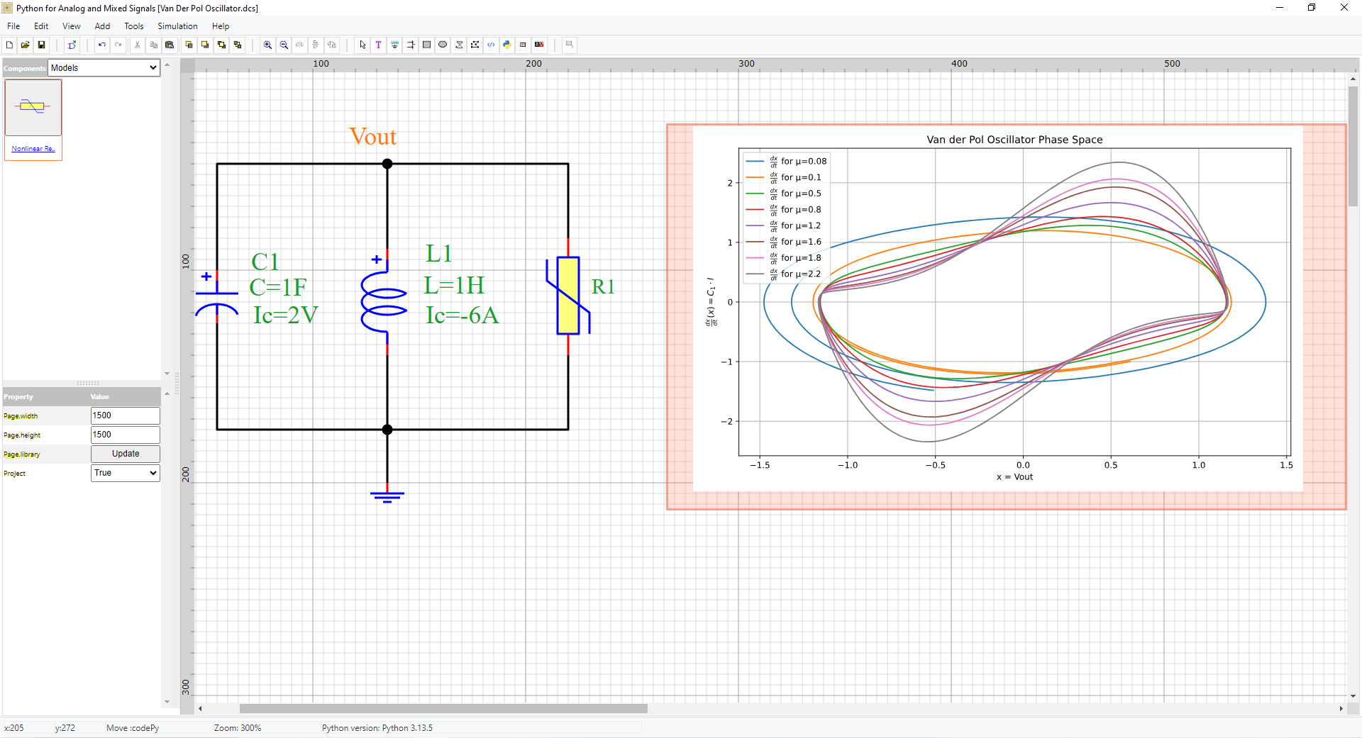
Figure 10 – Viewing and exporting simulation results.